
CASCADE™ High Power UHF Television Antenna
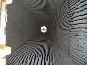
ERI CASCADE™ UHF television antennas come in top and side-mounted versions and are designed to optimize coverage for the mounting location and configuration. They are unpressurized and fully radome enclosed to provide stable performance under all environmental conditions. The build-up of icing is minimized due to natural shedding. The UV-protected, abrasion, and flame-resistant polycarbonate enclosure protects the antenna working elements to promote long, useful life. The CASCADE series includes models with horizontal, elliptical, or circular polarization. A vertically polarized component can enhance coverage and improve reception as more viewers opt to cut the cord and rely on over-the-air reception to receive the news and entertainment programming local broadcasters provide.
Features
- Custom Azimuth and Elevation Patterns Provide Coverage Tailored to Each Facilities Unique Requirements
- Horizontally, Elliptically and Circularly Polarized Models are Available Top-Mounted and Side-Mounted Configurations
- Top-Mounted and Side-Mounted Configurations
- High Null Fill and High Side Lobes Provide Increased Signal Levels
- Horizontal Plane Pattern Development Performed in ERI's Anechoic Chamber at Full Scale Provides Measured Performance of Antenna Radiated Pattern
- Computer Generated Elevation Pattern Design, Verified with near Field Measurement Speeds Fabrication and Tuning and Test Results Accurately Document Performance
Heavy Null Fill is Standard
The CASCADE is available with a wide variety of standard azimuth and elevation patterns to optimize signal in the desired coverage area. Customized patterns are available and are developed at full scale in ERI’s anechoic chamber to provide a measured horizontal plane pattern for customer approval before final fabrication is begun. ERI’s end-fed design minimizes complexity, maximizes power handling, and provides heavy null fill and electrical beam tilt without reducing elevation directivity. Eliminating internal power dividers increases power handling, and the more straightforward mechanical design improves reliability.
Complete Factory Testing
Directional azimuth patterns are often chosen for UHF antennas to optimize the viewing area’s coverage and maximize the antenna’s Effective Radiated Power (ERP) by using higher azimuth gains. Eliminating all extraneous signals from the measurements is essential, or significant errors can be introduced.
The appropriate conditions are accomplished using an anechoic chamber for azimuth pattern testing. The anechoic chamber is designed with absorbing material that covers the walls, ceiling, and floor to prevent unwanted reflections during the measurement procedure. It is a controlled measurement environment. It aims to represent the free space condition of the design criteria because it minimizes reflections and, at the same time, allows direct measurement of the azimuth pattern.
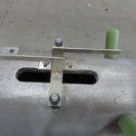
Determining the antenna’s elevation pattern requires the entire array to be assembled, and the phase and amplitude distribution across the aperture is measured. Because reflections and extraneous signals can cause significant errors in this measurement, ideally, the antenna should be placed inside an anechoic chamber, and the elevation pattern should be measured like the azimuth pattern. However, such a structure’s physical size and cost prohibit this in the UHF band. An alternate measurement method was developed to simulate the “free space” condition of the anechoic chamber. This near-field method uses an isolated probe to measure each slot’s slot excitation (amplitude and phase) in the array.
The process also includes direct measurement of the antenna VSWR at the antenna input to guarantee lower reflected power and optimum performance. Antenna fabrication is performed under procedures confirmed by a third-party certified quality management system. All welding is done by American Welding Society (AWS) certified personnel and checked by AWS-certified welding inspectors.
A heavy-duty internal DC ground across the inner conductor of the antenna protects against static build-up and lightning. The differential expansion between the inner and out conductors of the antenna is compensated with reliable field-proven bellows assembly. The fixed DC short has no finger stock or sliding contacts, so no periodic inspection or maintenance is associated with these elements. All top-mounted CASCADE antennas include four lightning rods that extend 3 feet (0.9 meters) above the beacon mount for additional protection from lightning strikes. Side-mounted antennas have two (2) lightning rods.
All ERI top-mounted television antennas have dedicated climbing facilities. This provides climbers superior access to the beacon and improves safety. The climbing ladder is made of fiberglass for non-directional elliptically and circularly polarized antennas to minimize the impact on the radiated pattern. The climbing apparatus is a galvanized steel climbing pole for horizontally polarized and directional antennas.
CASCADE™ High Power UHF Television Antenna Product Brochure

CASCADE™ High Power UHF Television Antenna
CASCADE™ UHF Television Antenna Azimuth Patterns
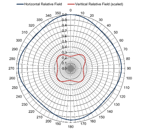
- Omnidirectional-
- H-Pol Dir:-1.19 (0.74 dB)
- V-Pol Dir:-1.49 (1.73 dB)
- PDF File
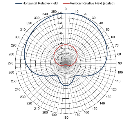
- SKULL-
- H-Pol Dir:-1.83 (2.61 dB)
- V-Pol Dir:-2.76 (4.42 dB)
- PDF File
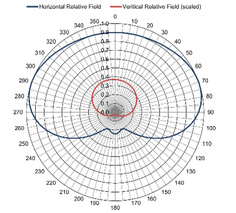
- C170-
- H-Pol Dir:-1.70 (2.31 dB)
- V-Pol Dir:-2.60 (4.16 dB)
- PDF File
CASCADE™ UHF Television Antenna Elevation Patterns

- 15H4 Horizontal and Vertical-
- Main Lobe:-15.00 (11.76 dBd)
- Horizontal:-12.37 (10.92 dBd)
- PDF File
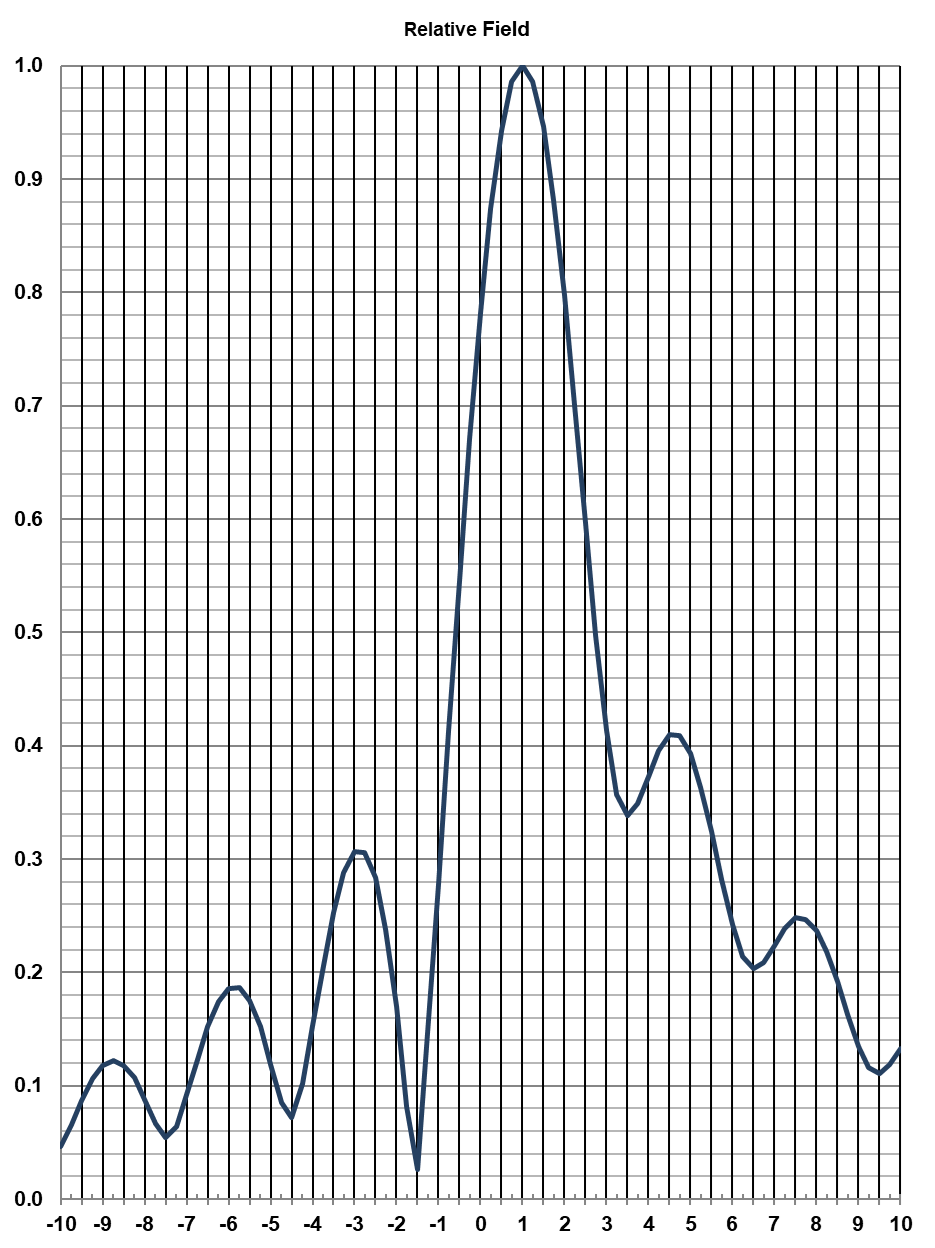
- 20H4 Horizontal and Vertical-
- Main Lobe:-20.00 (13.01 dBd)
- Horizontal:-12.23 (10.87 dBd)
- PDF File
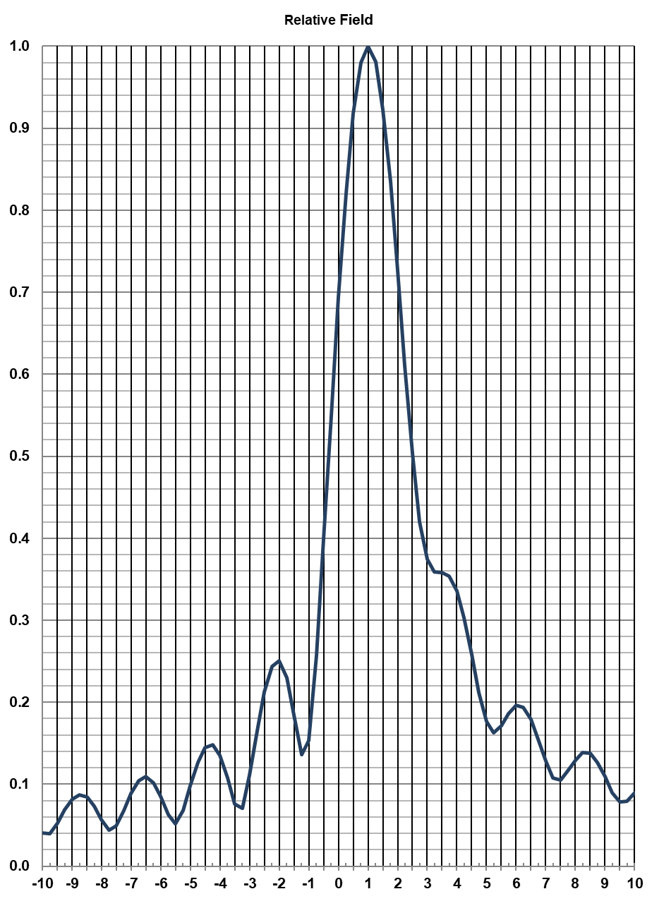
- 25H4 Horizontal and Vertical-
- Main Lobe:-25.00 (13.98 dBd)
- Horizontal:-12.06 (10.81 dBd)
- PDF File
The azimuth and elevation patterns shown represent the most common patterns requested. ERI has a large catalog of standard patterns and CASCADE® UHF television antennas are available with patterns customized to specific customer requirements. Contact ERI for information on an antenna built specifically for your application.