


Features

- Controls one or two motorized coaxial or waveguide switches
- An optional RF sensor connects to a built-in detector to prevent switch activation when RF is present
- Control and status connections made Cat-5 or Cat-6 ethernet cables with RJ45 connectors
- Switch selectable for 12V or 24V DC control voltage
- Built-in customer configurable SNMP control capabilities
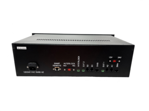
The EC130 switch controller is designed to operate either one or two industry-standard motorized coaxial or waveguide RF switches. The new EC130 motorized switch controller is designed to control one or two motorized switches and includes an SNMP interface. Adding an optional ERI Model VDM303 RF Power Detector, the EC130 will detect the presence of RF applied to the switch and prevent accidental switch activation while under power. The control interface and interlock connections are made with CAT5 or CAT6 cables with RJ45 connectors. The controller is contained in a 5.25-inch standard 19-inch rack-mountable chassis. The front panel, shown in figure 1 above, has menu navigation and parameter set buttons, a red/green LED that indicates the interlock closure status, and a switch lock. The rear controller panel, shown in figure 2, provides the status and control connection to the RF switch, a transmitter control interlock circuit, and a remote status and control interface. The transmitter control interlock circuit ensures that RF power is removed from the RF switch before changing its position. It will also prevent RF power from being applied when the switch is not locked in an operating position.