 The ERI 1180 Series Empire State Building Auxiliary FM Antenna is installed on Turntable No.2 at ERI’s Far-Field Antenna Test Range. The picture was taken during the acceptance testing witnessed by the owner and the users. This antenna is one of four (4) Master FM Antennas ERI has built and installed on The Empire State Building.
Category: Featured Projects
Evansville Courier & Press: Chandler antenna company marks 80 years in business
 The local Evansville newspaper featured an interview with ERI’s Tom Silliman to recognize ERI’s 80 years in business. You can read the article here: Courier & Press ERI Celebrates 80 Years
RadioWorld Great RF Installs eBook Published!
 Check out the Great RF New RF Installs eBook from RadioWorld. https://www.radioworld.com/resource-center/ebooks/we-release-great-new-rf-installs-ebook You can access it here: RW Great RF Installs ebook – July 2023
NECRAT.US features WEOW (FM) and WAIL (FM) serves Key West with an ERI 12-Bay ROTOTILLER®

 An ERI twelve-bay diplexed ROTOTILLER® FM antenna transmits WEOW (FM) and WAIL (FM), both Class C1 FMs with a 100 kW ERP. The antenna has a branch feed system to improve the system bandwidth. The 12-bay array combines two six-bay center-fed arrays into a single input. The antenna is designed so that co-owned WCNK (FM), 98.7 MHz, and WWUS (FM), 104.1 MHz, could also operate from this antenna. The FM channel combiner feeding the antenna is an FM junction combiner consisting of two ERI 783 FM bandpass filters. The tower was also designed and manufactured by ERI. It is a 57-inch face 600-foot structure manufactured and installed by ERI in 2012—photo courtesy of Mike Fitzpatrick. More great photos are found here.
Starting final tuning and assembly for a new six (6) station constant impedance FM channel combiner

The cavities, resonators, and transmission line components for a new six (6) station constant impedance FM channel combiner are complete. They are now in ERI’s Filter Lab for setup, tuning, and final assembly. The system should be done, and the final test and performance data will be taken by the end of the month. The eight-bay AXIOM® Master FM Antenna will be ready for final tuning soon.
A new 6-Bay ROTOTILLER® Being Packed for Shipment
Pictured are four bays of an ERI Model SHPX-6AC six-bay FM antenna in packing before shipment. The packaging includes a support cradle for each individually boxed antenna bay to support it through transit and protect it from damage.
FM Bandpass Filter Cavities for a New FM Channel Combiner
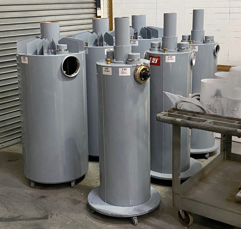
These are bandpass filters for a new FM Tee Combiner for two FM stations in Missouri. The two three-section bandpass filters will combine the two stations and feed a new diplexed eight-bay ROTOTILLER® FM antenna. Most of the ROTOTILLER FM antennas built by ERI are made for only one FM channel and transmit a single channel. The antenna can also be designed to transmit two, three, or more FM stations from one antenna. In this case, the two FM stations are 13 MHz apart. The SHPX-8C3-SP FM antenna consists of two four-bay center-fed arrays combined with an additional center feed.
A new Three-Bay LPX ROTOTILLER® FM Antenna
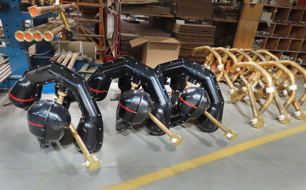
A new three-bay end-fed LPX-3E ROTOTILLER® FM antenna is ready for packing and shipment. This particular antenna is bound for an FM station in Northwestern Pennsylvania just south of the PA-NY state line. The radomes provide protection from snow and ice accumulation which can be heavy in that region.
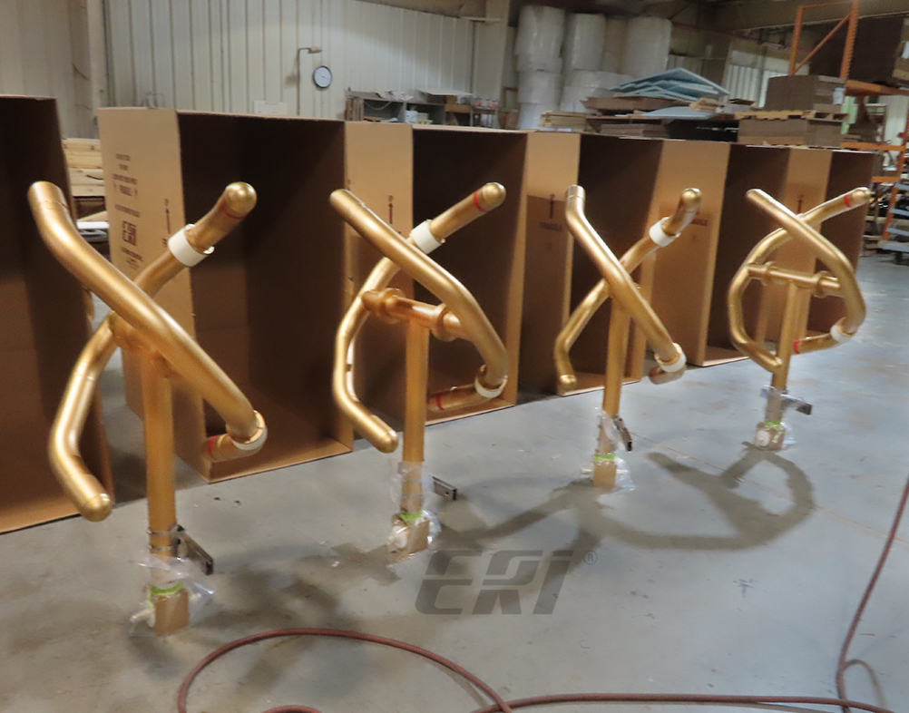
Finishing a Batch of New ROTOTILLER® FM Antennas

An LPX-6C six-bay low-power ROTOTILLER® FM antenna finished tuning, painted, and ready to be packed for shipment along with the LPX-2E, with optional radomes, also prepared to be packed and shipped for another customer. On the far right is the last bay of a new SHPX-10AC high-power ROTOTILLER® FM antenna bound for North Dakota by the end of this week.
ERI’s Test Range Experience Delivers Accurate Results

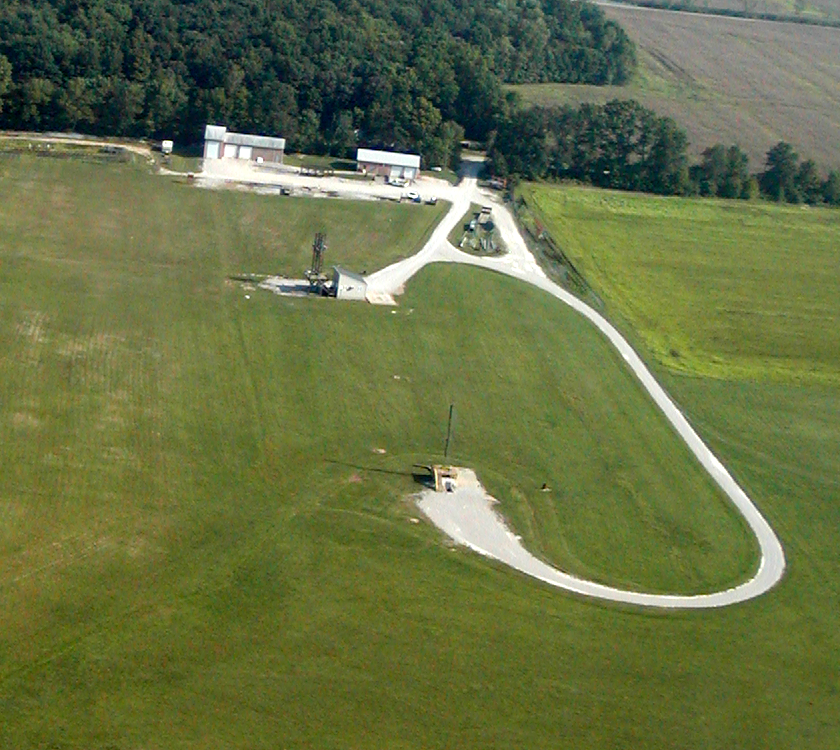
ERI’s Antenna Test Range has been in continuous use longer than any other Test Range used by any broadcast antenna supplier. This is important because long experience is needed to fully characterize a test facility so that it delivers accurate results. This process requires years and newly constructed antenna test facilities cannot be trusted to provide accurate and repeatable measurements.
The range includes two turntables and one static stand. The turntables are rated for deadweight loads of 12,000 and 25,000 pounds – respectively. In addition to the range measurement and test facilities, the site includes a machine shop and fabrication facility for constructing replica tower sections independent of ERI’s main factory. The test site is also equipped with a static stand workstation for the setup and tuning of Batwing television antennas and Master FM Antenna Systems. The ERI test range has its own dedicated staff of tower climbers, machinists, technicians, and engineers