CY310 High Band VHF Switchless Combiner
Any High Band VHF Channel 174 to 250 MHz
2 x 20 kW average power
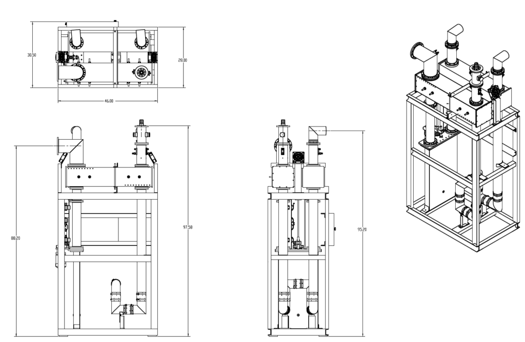
The Switchless Combiner system consists of two 3 dB hybrid couplers and a motorized, 3-postion phase-shifter. The combiner system is fully integrated and resides in an aluminum floor-mount base. The input connections are both 4-1/16-inch, 50 ohm unflanged, female. The combined output is 6-1/8-inch EIA flanged, male and the reject load port is 4-1/16-inch flanged, male. Test/reject load is customer supplied.
Switchless Combiner Modes:
A to Air and B to Load
B to Air and A to Load
A + B to Air
- (2 each)3-dB Coaxial Hybrid Coupler
- (1 each)Motorized, 3-position Coaxial Phase Shifter (0, 90, 180 degrees)
- (1 each)1-port Directional Coupler, 4-1/16-inch (at reject load port)
- (2 each)1-port Directional Coupler, 4-1/16-inch (at combiner inputs)
- (1 each)6-1/8-inch, 50-ohm, EIA Flanged Male (at antenna output)
- Interconnect components between above items
- Floor-mount base frame
- Switchless Combiner System does not include Reject Load
CY310 Product Specifications
- Input Power:2 x 20 kW average power, ATSC 1.0
- Output Power:40 kW Average, ATSC 1.0
- Frequency:174 to 250 MHz
- Tuned to designated 6, 7 or 8 MHz RF channel
- Input Connectors:4-1/16-inch, 50-ohm, Flanged Male
- Output Connectors:4-1/16-inch, 50-ohm, Flanged Male (load)
- 6-1/8-inch, 50-ohm, EIA Flanged Male (antenna)
- VSWR:1.08 : 1 or better over channel
- 1.15 : 1 or better over channel (during changeover)
- Insertion Loss:0.20 dB max over channel
- Input Isolation:30 dB min. over channel
- Coupler Directivity:32 dB min. over channel
- AC Power:120 or 240 VAC, 60Hz, < 600VA
- DC Control Power:12 or 24 VDC, 75 MA
- Ambient Temperature:14 to 122 degrees F (-10 to 50 degrees C)
- Ambient Humidity:0 to 95% Relative, non-condensing
- Altitude:0 to 5,000-feet AMSL (0 to 1,524-meters AMSL)
CY310 Outline Drawing